About the Product
Current transformers are designed to convert high primary current levels into secondary currents of a lower, more manageable magnitude — typically 5 Amperes or 1 Ampere. This enables seamless integration with measuring instruments and protection devices such as relays that monitor primary current levels.
Where connecting leads are exceptionally long, a 1 Ampere secondary is preferred to reduce the VA burden on the transformer and preserve measurement accuracy.
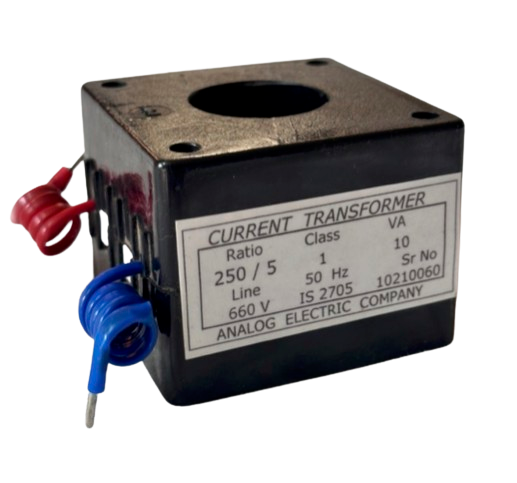
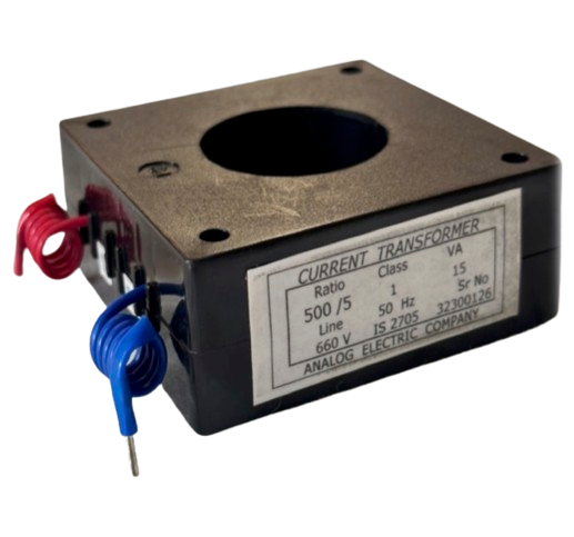
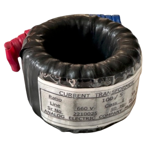
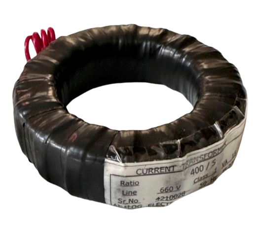
All CTs are constructed using premium Cold-Rolled Grain-Oriented (CRGO) silicon steel, formed into a toroidal shape without joints for optimal accuracy. Coils are wound with high-quality electrical-grade copper, with interlayer insulation from polyester tape. Final encapsulation is by ABS moulding, resin casting, or PVC taping depending on application requirements.
CE Mark
Directive 2009/125/EC
Cert No. US-AGCY-24-04252 · Valid to Apr 2027
Types of Current Transformers
Metering Current Transformers
Engineered for accuracy in power measurement systems, supplying calibrated signals to ammeters, watt meters, and energy meters. Accuracy classifications range from 5% to 120% of nominal current ratings. Designed to reach saturation between 150% and 200% of rated current, protecting connected instruments from damaging current spikes during system anomalies.
Core Balance Current Transformers
Used in conjunction with earth fault relays to detect earth fault currents. The core balance configuration monitors all phase conductors simultaneously, enabling reliable detection of leakage currents and providing a critical layer of protection in industrial distribution systems.
Construction Types
Bar Primary CTs
Comprises secondary windings only. Mounted onto a bus bar, which serves as a single-turn primary conductor. Recommended for rated currents of 100 Amperes and above, where adequate ampere-turns are available to compensate for losses and achieve 1% accuracy or better.
Wound Primary CTs
Equipped with both primary and secondary windings. The primary winding is configured with sufficient turns to achieve the necessary ampere-turns, making these suitable for lower current ratios and applications requiring 1% accuracy or finer.
Enclosure options: PVC Wound Tape and ABS Moulded Case. Comprehensive routine testing is performed on every unit with detailed test reports available on request.
Applications
Analog Electric current transformers are used across a wide range of metering, protection, and monitoring applications in industrial and commercial electrical installations.
APPLICATION
Energy Metering
Supplying calibrated current signals to KWH, KVAR, and power factor meters in energy management and billing systems.
APPLICATION
Protection Relays
Feeding current signals to overcurrent, earth fault, and differential protection relays to detect fault conditions and isolate equipment.
APPLICATION
Panel Meters & Ammeters
Providing safe, scaled current inputs to digital and analog panel meters for real-time current display on distribution boards and MCCs.
APPLICATION
SCADA & Monitoring
Integrating with SCADA systems and power monitoring equipment for real-time electrical parameter tracking and demand management.
APPLICATION
Power Quality Analysis
Supporting power quality analysers and recording instruments to measure harmonic distortion, unbalance, and demand profiles.
APPLICATION
Earth Fault Detection
Core balance CTs used with earth fault relays to detect leakage currents and provide protection against earth faults in distribution systems.
Limits of Error per Accuracy Class
Per IS2705-1992. Values shown as percentage of rated current at 120%, 100%, 20%, and 5% of rated current.
| Class of Accuracy | Ratio Error % at % of Rated Current | Phase Error (min) at % of Rated Current | ||||||
|---|---|---|---|---|---|---|---|---|
| 120% | 100% | 20% | 5% | 120% | 100% | 20% | 5% | |
| 0.1 | 0.1 | 0.1 | 0.2 | 0.4 | 5 | 5 | 8 | 15 |
| 0.2 | 0.2 | 0.2 | 0.35 | 0.75 | 10 | 10 | 15 | 30 |
| 0.5 | 0.5 | 0.5 | 0.75 | 1.5 | 30 | 30 | 45 | 90 |
| 1.0 | 1.0 | 1.0 | 1.5 | 3 | 60 | 60 | 90 | 180 |
• For Class 3: Ratio Error 3% at 50% and 100% of rated current
• For Class 5: Ratio Error 5% at 50% and 100% of rated current
• No phase error specified for Class 3 and Class 5
Typical VA Burdens of Common Instruments
Use these reference values when selecting the appropriate CT burden for your application. Recommended cable: 7/029, which gives 0.05 VA/ft for 5A and 0.002 VA/ft for 1A secondary.
| Instrument | VA |
|---|---|
| Ammeter | 3 |
| Current coil of KWH & KVAR meters | 5 |
| Current coil of recording PF meter, KWH & KVAR meters | 5 |
| Current coil of wattmeter & power factor meter | 5 |
| Recording ammeters | 3 |
Part Number Reference
Analog Electric part numbers encode the enclosure type, secondary current, primary configuration, and current ratio in a standardised format. See below for the naming convention.
Low Tension Moulded Case — Bar Primary
All dimensions in mm. Tolerance ± 3 mm.
| Part No | Ratio | Burden (VA) | Cl | Inner Dia (mm) | Outer Square (mm) | Thickness (mm) |
|---|---|---|---|---|---|---|
| MC 5 BP 50 | 50/5 | 5 | 3 | 32 | 70×70 | 53 |
| MC 5 BP 60 | 60/5 | 5 | 3 | 32 | 70×70 | 53 |
| MC 5 BP 75 | 75/5 | 5 | 3 | 32 | 70×70 | 53 |
| MC 5 BP 100 | 100/5 | 5 | 1 | 32 | 70×70 | 53 |
| MC 5 BP 150 | 150/5 | 5 | 1 | 32 | 70×70 | 53 |
| MC 5 BP 200 | 200/5 | 10 | 1 | 32 | 70×70 | 53 |
| MC 5 BP 250 | 250/5 | 10 | 1 | 45 | 94×94 | 35 |
| MC 5 BP 300 | 300/5 | 10 | 1 | 45 | 94×94 | 35 |
| MC 5 BP 400 | 400/5 | 15 | 1 | 62 | 113×113 | 35 |
| MC 5 BP 500 | 500/5 | 15 | 1 | 62 | 113×113 | 35 |
| MC 5 BP 600 | 600/5 | 15 | 1 | 62 | 113×113 | 35 |
| MC 5 BP 800 | 800/5 | 15 | 1 | 62 | 113×113 | 35 |
Low Tension Tape Wound — Bar Primary
All dimensions in mm. Tolerance ± 3 mm. For 3000A and above: dimensions as per bus bar size on request.
| Part No | Ratio | Burden (VA) | Cl | Inner Dia (mm) | Outer Square (mm) | Height (mm) |
|---|---|---|---|---|---|---|
| T 5 BP 1000 | 1000/5 | 15 | 1 | 105 | 140 | 35 |
| T 5 BP 1200 | 1200/5 | 15 | 1 | 105 | 140 | 35 |
| T 5 BP 1600 | 1600/5 | 15 | 1 | 115 | 165 | 35 |
| T 5 BP 2000 | 2000/5 | 15 | 1 | 115 | 165 | 35 |
| T 5 BP 2500 | 2500/5 | 15 | 1 | 130 | 190 | 35 |
Low Tension Wound Primary Type
All dimensions in mm. Tolerance ± 3 mm.
| Part No | Ratio | Burden (VA) | Cl | Length (mm) | Width (mm) | Height (mm) |
|---|---|---|---|---|---|---|
| WPL 5 WP 1 | 5 / 1 A | 5 | 1 | 92 | 66 | 45 |
| WPL 5 WP 5 | 5 / 5 A | 5 | 1 | 92 | 66 | 45 |
| WPL 50 WP 1 | 50 / 1 A | 15 | 1 | 92 | 66 | 45 |
| WPL 50 WP 5 | 50 / 5 A | 15 | 1 | 92 | 66 | 45 |
Need a custom ratio or enclosure type?
Contact our Instrument Transformers Division or submit your specifications for a detailed quote.